the Creative Commons Attribution 4.0 License.
the Creative Commons Attribution 4.0 License.
 | 22 Apr 2020
About geomechanical safety for UGS activities in faulted reservoirs
Claudia Zoccarato
Massimiliano Ferronato
Andrea Franceschini
Matteo Frigo
Carlo Janna
Giovanni Isotton
A critical issue concerning geomechanical safety for UGS (underground gas storage) in compartmentalized reservoirs is fault reactivation. Indeed, the displacement (land subsidence, land upheaval) and the stress fields caused by the seasonal injection and production of CH4 into and from deep reservoirs is peculiar. The need of improving our understanding of compartmentalized reservoir behavior and to define safe bounds for the pressure fluctuation in order to prevent undesired land movements and induced seismicity is becoming even more important. This also in view of the expected energy transition when large amount of green energy will potentially be stored and recovered through UGS of compressed air or hydrogen. In this framework, an in-depth modelling investigation has been carried out for the typical UGS geological setting and operations in The Netherlands. The specific goals of the study are the following: (i) explaining the possible mechanisms responsible for seismic events unexpectedly recorded during UGS phases; (ii) understanding which are the critical factors (e.g. the geological configuration, the geomechanical properties, and the reservoir operations) that increase the probability of fault reactivation during the various UGS stages; and (iii) advancing possible guidelines for safe UGS operations. This contribution summarizes the main outcomes obtained by the modelling simulations: the combinations of factors causing fault reactivation during primary production (PP) are also more prone to generate fault failure during cushion gas injection (CG) and UGS. In fact, fault activation during PP leads to a stress redistribution and a new (deformed) “equilibrated” configuration that is newly loaded, in the opposite direction, when the pressure variation changes the sign because of CG and/or UGS. Finally, the various combinations have been ranked to highlight the conditions where the fault system is most likely reactivated during CG and UGS operations: the initial stress regime of the system, the geomechanical properties of the fault, and dislocation of the reservoir compartments are the major influencing drivers to fault instability.
- Article
(569 KB) - Full-text XML
- BibTeX
- EndNote


Induced seismicity is become a major issue in fluid production from and injection into deep formations. Apart from fracking, where low-permeability formations are intentionally fractured to increase productivity, thus (micro-) seismicity are an inevitable consequence of a successful project (e.g., Farahbod et al., 2015), several seismic events caused by “conventional” removal or injection of diverse fluids are listed in specific databases, such as HiQuake (https://inducedearthquakes.org/, last access: 1 March 2020), and related publications (e.g., Foulger et al., 2018).
Seismicity induced by fluid removal from faulted formations is somehow “expected” when the extracted volumes or the associated pressure decline overcome a certain bound (Fig. 1a). McGarr (1991) suggested that net extraction of oil and water reduced the average density of the upper crust, thus decreasing the normal stress that prevents slip of faults. In compartmentalized gas reservoirs, seismicity has been reported when large pressure declines cause significant differential compaction between produced and unproduced blocks, i.e. large increase of the shear stress on the sealing faults between the compartments (van Eck et al., 2006). Nicholson and Wesson (1992) suggested that an earthquake might occur in response to larger stresses imposed by fluids migrating into the mid-to-lower crust. The change in pressure resulting from withdrawal of oil induces fluid migration within non-sealing faults that brought the faults closer to failure because of the reduced effective stress normal to the discontinuity surfaces and the deterioration of the fault mechanical properties (i.e., a decrease of the friction angle).
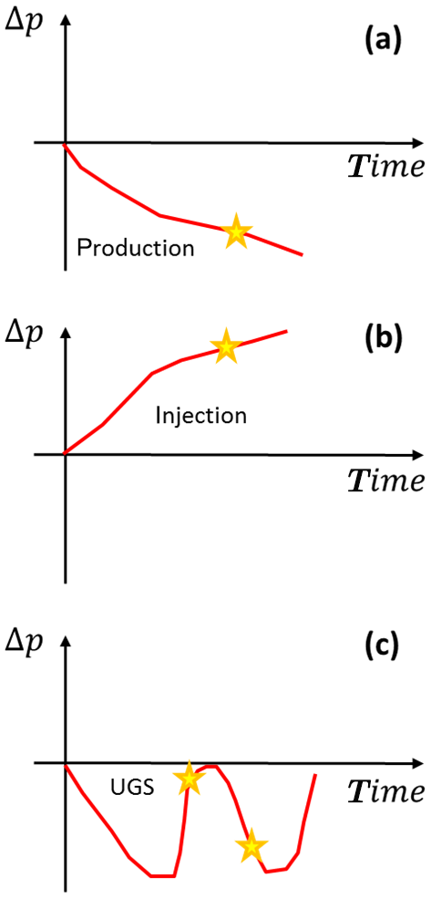
Figure 1Sketch of “expected” and “unexpected” seismic events. “Expected” seismicity can occur during (a) hydrocarbon primary production (PP) and (b) during fluid injection when the pore pressure depletion or increase, respectively, overcomes a certain threshold. (c) “Unexpected” seismicity can occur during cushion gas injection (CG) and underground gas storage/injection (UGS) UGS when the pore pressure is comprised between the value in initial undisturbed condition and the minimum at the end of PP.
According to the Mohr-Coulomb criterion, also the introduction of fluids into faulted reservoirs is expected to encourage fault failure (Fig. 1b). A number of cases of seismic activity has been associated to geologic CO2 sequestration (e.g., Verdon et al., 2013) and wastewater disposal (e.g., Ake et al., 2005). The explanation of these seismic occurrences has been provided by Vilarrasa et al. (2019): the over-pressurized fluid flows within the faults, decreasing the normal stress acting on the discontinuities that are consequently re-activated.
Induced seismicity cannot be explained by “simply” invoking the Mohr-Coulomb criterion when an event develops in correspondence to a fluid pressure distribution already experienced by the geologic system. This is the typical condition of UGS reservoirs where the pore pressure fluctuates seasonally between a maximum Pmax and a minimum Pmin values due to CH4 injection during summer and withdrawal during in winter (Fig. 1c). A certain seismic activity has been recorded in a few faulted UGS fields in The Netherlands, toward the end of the primary production (PP), at the end of the cushion gas (CG) injection (when the pressure returns approximately to the natural value because a volume of gas is injected in an underground storage reservoir to provide the necessary pressure to deliver working gas volumes to customers), or during injection of gas within the UGS cycles (TNO, 2015; NAM, 2016).
In this framework, the main goal of the study is (i) to understand which the mechanisms are responsible for this “unexpected” seismicity, and (ii) consequently provide some considerations about the possibility of safe UGS activities, i.e. seasonally storing gas into and producing gas from UGS fields reducing the risk of re-activating the faults bounding and/or crossing the reservoir.
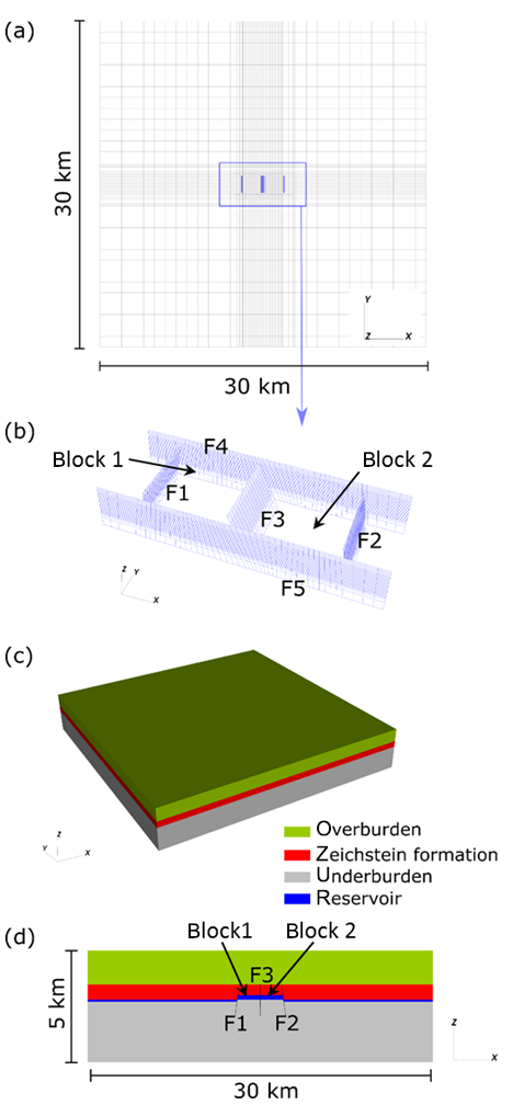
Figure 2Conceptual model and model discretization: (a) plan view of the model with the FE (in black) and IE (in blue) discretization; (b) IE discretization of the fault discontinuities. F1, F2 and F3 are parallel to the y-axis whereas F4 and F5 to the x-axis; (c) perspective view and (d) vertical cross section through the reservoir of the model domain with the various geologic units highlighted by different colours.
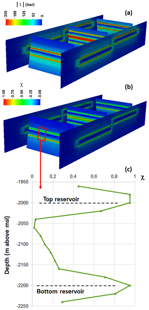
Figure 3Scenario 3d: distribution of (a) and (b) criticality index χ on the fault system at the end of PP. The depth distribution of χ along fault F1 is shown in (c).
2.1 Conceptual model
A set of numerical simulations has been carried out to investigate the processes of interest. The geological setting, geometric features, and production history typical of UGS reservoirs in The Netherlands have been used (e.g., Fokker et al., 2016; Wassing et al., 2017).
The reservoir is made of two adjacent square blocks, 2000×2000 m wide, confined laterally by four faults, namely F1, F2, F4 and F5 (Fig. 2). Another fault, F3, subdivides the reservoir in two compartments, so that the pore pressure changes ΔP1 and ΔP2 in the two compartments can differ. The reservoir is embedded in a 30 km wide square domain. Faults F4 and F5 are vertical, F1 and F2 are inclined with a dip angle equal to ±10∘. The dip angle of fault F3 can vary. The reservoir is 200 m-thick and 2000 m deep. The bottom of the model is 5000 m deep and the land surface has an elevation of 0 m. The faults extend from −3000 to −1500 m depth, i.e. they terminate within the caprock sealing the reservoir (Zeichestein formation). Block 2 can be offset in the vertical direction of 100 and 200 m, corresponding to half the thickness and the entire thickness of the reservoir (Fig. 2).
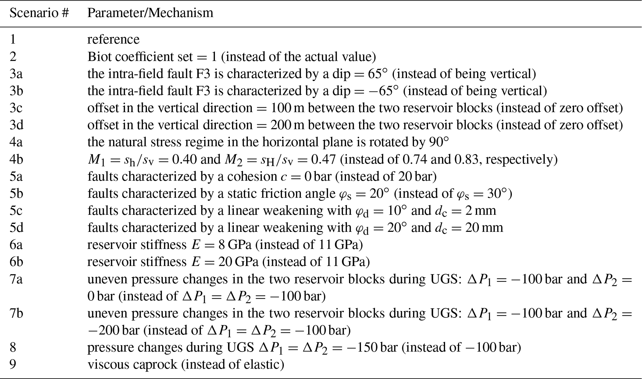
Table 1Scenarios addressed in the sensitivity analysis. M1 and M2 are the ratios between the minimum and maximum horizontal principal component of the natural effective stress regime and the vertical principal component, respectively.
2.2 Set-up of the numerical model
A 3D hexahedral finite element (FE) – interface elements (IE) mesh is developed (Fig. 2). The mesh consists of 253 165 nodes and 236 208 FEs with a finer discretization in the reservoir layers, i.e., at depth between 1800 and 2200 m. The element size within the reservoir is m. IEs, which are zero-thickness FEs composed of two surfaces that can slide or move apart one from each other when a failure criterion is overcome, have been integrated into the 3D FE mesh. Figure 2b shows the fault system embedded in the continuous 3D grid. An overall number of 5215 IEs is used to discretize the five faults.
Stress and strain fields associated to UGS have been simulated using the M3E_GEPS3D (Geomechanical visco-Elasto-Plastic Simulator – 3D) simulator, an in-house developed code (Spiezia et al., 2017; Isotton et al., 2019). The code simulates the possible activation of pre-existing faults with a quasi-static approach. The discontinuity surfaces are modelled according to the principles of contact mechanics as inner boundaries embedded in the continuous body. IEs are implemented for fault discretization (Franceschini et al., 2016, 2019).
The rupture activation is governed by the Mohr-Coulomb failure criterion (Labuz and Zang, 2012), i.e. a fault reactivation occurs whenever the shear stress exceeds the limiting value τL:
with σn and τ the normal and shear stresses, respectively, acting on the fissure surfaces, ϕ and c the fault friction angle and cohesion, respectively. The principle of “Maximum Plastic Dissipation” is used to define the direction of the limiting shear stress. The pore pressure variation within the faults is the average between the values experienced by the two adjacent portions separated by the discontinuity.
Standard conditions with zero displacements on the outer and bottom boundaries are prescribed, and the land surface is a no-stress boundary.
2.3 Simulated scenarios
The model has been initially applied to the so-called reference scenario, i.e. a scenario based on the typical characteristics of the UGS reservoirs in the Netherlands. The two reservoir blocks experience a pressure change ΔP amounting to −200 bar over a 10-year PP phase. PP is followed by a 2-year CG injection phase when the pressure recovers to the initial (undisturbed) value Pi and then UGS cycles characterized by a 6-month production phase, during which bar, and a 6-month injection period when the pressure returns to Pi. For a detailed description of the reference scenario, see Teatini et al. (2019).
Then, a sensitivity analysis has been developed to understand the geometric features, geomechanical parameters, and pressure distributions that make the fault system likely to be reactivated during CG and UGS. Firstly, each parameter characterizing the system has been varied at a time. In a second stage, simultaneous modifications of various parameters of the reference set-up have been addressed. The various scenarios addressed by the sensitivity analysis are summarized in Table 1. Notice that only likely configurations have been tested. The aim of the study is not to analyse “extreme” conditions.
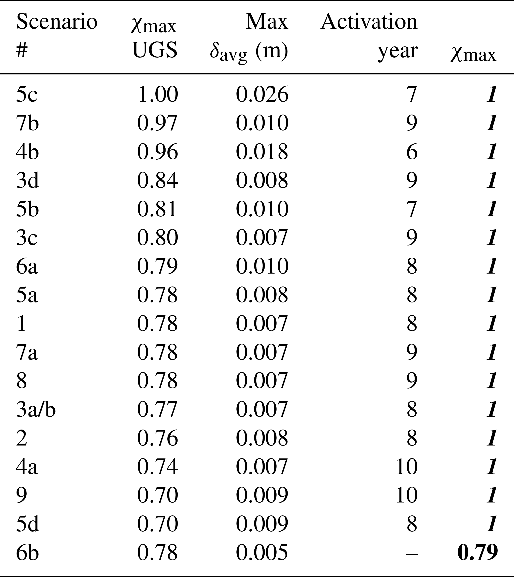
Table 2Fault F2: ranking of the simulated scenarios, from the most to the least prone to induce subsidence during CG and UGS phases, using criterion 1a. χmax is the maximum value of the criticality index during the whole reservoir life, i.e. including PP. The fonts bold-italic, bold, and italic are used to characterize a critical, almost critical, and safe condition, respectively.
3.1 Outcome of the numerical model
The model results provide the 3D displacement and stress fields on each nodes of the 3D grid. In this study, the main interest is focused on the IE solution and, specifically, on the stress conditions and eventually sliding of the discontinuity surfaces.
Two parameters are used to quantify the fault state in relation to their possible reactivation. Firstly, the criticality index , which represents the ratio between the actual tangential stress τ acting on a fault and the limit tangential stress τL according with the Mohr-Coulomb criterion. When χ=1.0 the fault starts sliding. The second one is t80, i.e. the fault thickness with a criticality index χ>0.8.
An example of and χ distribution at year 10 for the scenario 3d is provided in Fig. 3. Consistent with previous modelling outcomes (e.g., Wassing et al., 2017), fault reactivation develops mainly at the top and bottom of the reservoir formation and propagates over a short distance into the caprock.
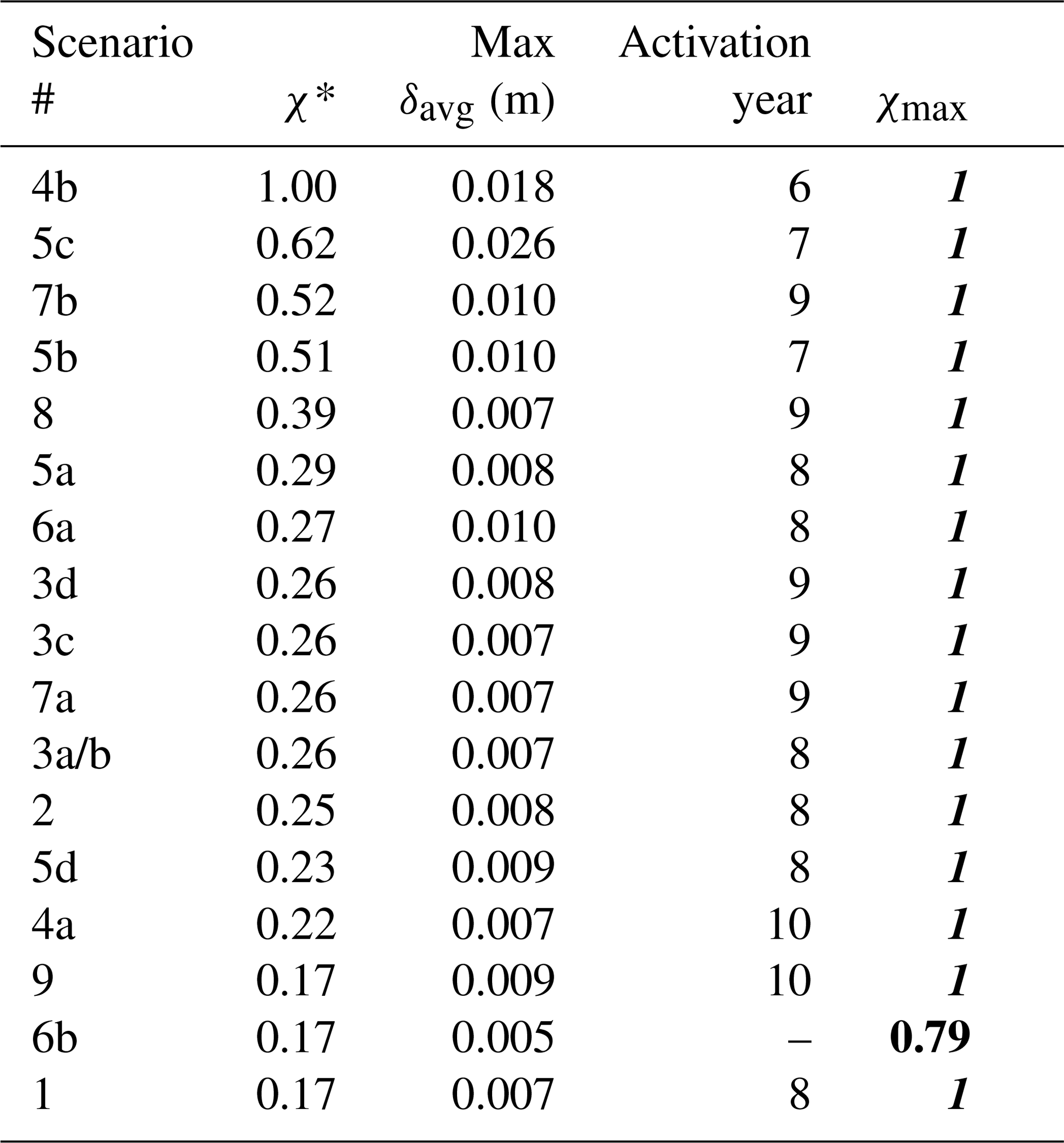
Table 3Fault F2: ranking of the simulated scenarios, from the most to the least prone to induce subsidence during CG and UGS phases, using criterion 1b.
3.2 Processes responsible for “unexpected” seismicity
The modelling outcome reveals that the scenarios causing fault reactivation during PP are more prone to fault failure during CG injection and UGS. Indeed, reversing the sign of the pressure change when only elastic deformations developed (i.e., no fault has been activated) causes the system to be unloaded, returning to the original stress regime. Conversely, fault activation during primary production (generally at the end of this development phase in the scenarios addressed in this study) leads to a stress redistribution and a new (deformed) “equilibrated” configuration that is newly loaded, in the opposite direction, when the pressure increases due to CG injection.
The faults approach a critical stress state during CG and UGS generally at the end of the injection/production phases when the cumulative pressure change – both decreasing and increasing – reaches the largest value.
Inspection of the results allows pointing out that the initial stress regime can play a major role: a significant decrease of the horizontal principal components, as tested in scenario 4b, favours an early fault reactivation. Other main factors yielding the faults close to failure are a reduced friction angle (scenarios 5b and 5c), a large dislocation between producing compartments (scenario 3d), a significant difference between the reservoir stiffness and that characterizing the caprock, sideburden, and underburden (scenario 6a), and an uneven pressure change within adjacent compartments (scenarios 7a and 7b).
3.3 Ranking the conditions prone to “unexpected” seismicity
Post-processing of the modelling outcomes has been aimed at defining a methodology to rank the mechanisms, geological settings, geomechanical and production parameters in relation to their potentiality of inducing “unexpected” seismic events. The sensitivity scenarios have been ranked following these nested criteria:
-
(a) χmax during UGS; or (b) normalized over max(χ∗)|scenarios where te is the element area. χ∗ is indicative of the fault extent where activation is close to occur;
-
maximum value of average sliding (δavg), evaluated on active elements only;
-
loading step of activation, i.e. the minimum pressure change causing fault activation.
The analysis has been carried out for the central fault F3 and fault F2 that is representative of the discontinuities bounding the reservoir. Notice that fault F3 is inactive in some of the investigated scenarios because of symmetry in the geological setting and driving forces.
Table 4Fault F3: ranking of the simulated scenarios, from the most to the least prone to induce subsidence during CG and UGS phases, using criterion 1a. χmax is the maximum value of the criticality index during the whole reservoir life, i.e. including PP. The fonts bold-italic, bold, and italic are used to characterize a critical, almost critical, and safe condition, respectively.
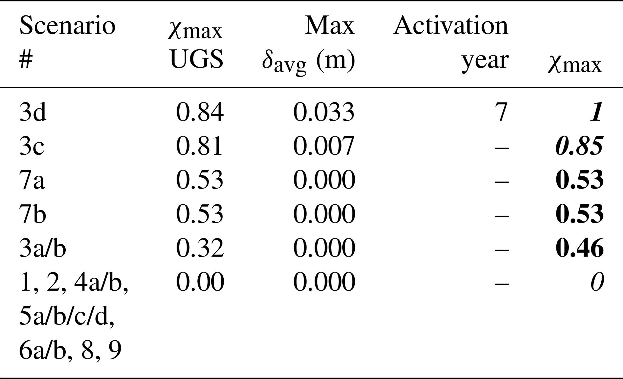
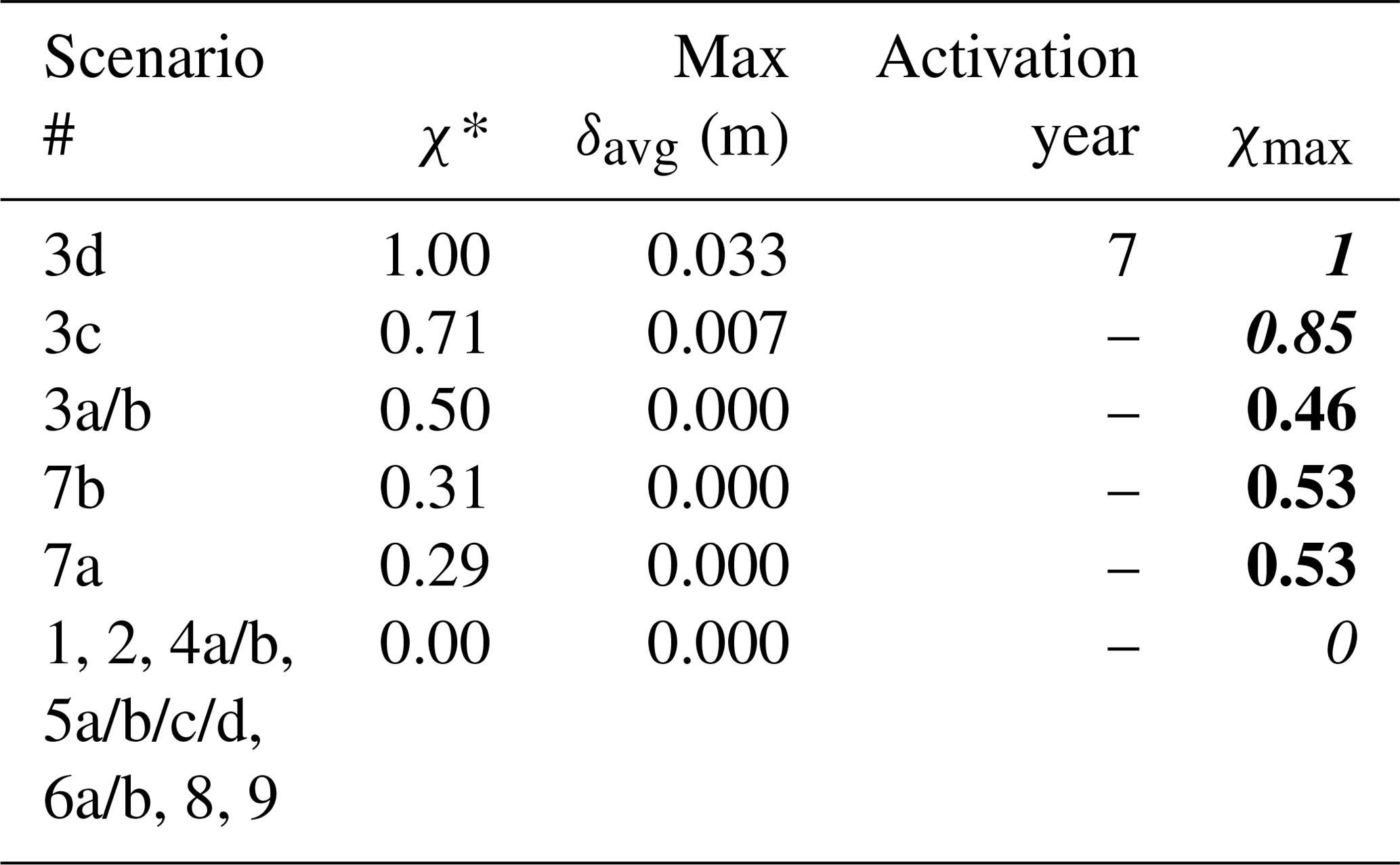
The results of the two ranking procedures are reported in Tables 2 and 3 for fault F2, and in Tables 4 and 5 for fault F3. It is interesting to note that the ranks obtained with the two criteria are similar which means that, when , fault reactivating is very likely to occur. As expected, the critical factors influencing fault activation during CG and UGS cycles arranges differently for the boundary and central faults. On fault F2, the stability is mainly jeopardized by the initial stress regime of the system, the geomechanical properties of the system (e.g., reservoir stiffness) and the characteristics of the faults (cohesion, static friction angle, presence of fault weakening). Due to symmetry conditions of fault F3 for most of the scenarios, the major influencing drivers to fault instability are given by geometrical parameters characterizing the fault/reservoir system (Tables 4 and 5). Dislocation of the reservoir compartments, non-vertical fault plane, different pressure changes in the two compartments, and fault dip are the features threating the stability of the fault F3.
It is worth noting the results of the scenario with a viscous caprock (scenario 9). Conversely to results obtained by previous modelling studies (e.g., Wassing et al., 2017), Tables 2 and 3 reveal that the presence of a salt viscous formation sealing the top of the reservoir is not a key parameter in favoring fault reactivation. This difference with previous outcomes, which were focused on production reservoirs, is likely due to the short-term (seasonal) fluctuation of the pressure change in the underlying UGS reservoir that limits the full development of the viscosity effect. However, it must be specified that the caprock discretization used in this 3D modelling study (20 m along the vertical direction) is one order of magnitude larger than those used in 2D investigations specifically devoted to the caprock behavior. The relatively large mesh could smooth the viscous effects.
Table 5Fault F3: ranking of the simulated scenarios, from the most to the least prone to induce subsidence during CG and UGS phases, using criterion 1b.
The numerous scenarios investigated within the study have clearly revealed that fault reactivation can occur during CG (cushion gas) injection and UGS (underground gas storage), and is more likely if seismicity has been recorded during PP (primary production). Although the results are qualitative because of the theoretical/general framework of the modelling applications, preliminary “suggestions” can be sketched to avoid potential induced seismicity during CG and UGS.
A limitation on the maximum pressure Pmax (below the initial pore pressure) at the end of CG and UGS injection should be prescribed depending on the geometry of the fault/reservoir: the presence of sloped faults, dislocation of the reservoir compartments, differential pore pressure between adjacent reservoir compartments and within each reservoir block are critical factors to be accounted for to define a safe Pmax bound. A large difference between the reservoir and caprock stiffness is also a criticality factor that can threaten the fault stability. In these conditions, limitations on the operational pressure fluctuation during a UGS cycle and on the rate of pressure recovery during CG injection should be properly prescribed depending on the specific reservoir features.
Specific investigations are also fundamental to characterize the reservoir setting and thereby to avoid or reduce the risk during operations. Importance should be given to improve the knowledge on the following aspects (from the most to the least importance):
-
the initial stress regime of the faulting system;
-
the reservoir stiffness;
-
the geomechanical parameters of the faults (failure criterion);
-
the reservoir permeability (or, equivalently, the pore pressure distribution within the reservoir compartment).
Data are available by writing to the corresponding author.
All the authors contributed to design the modelling study, develop the numerical analyses, and write the paper.
The authors declare that they have no conflict of interest.
This article is part of the special issue “TISOLS: the Tenth International Symposium On Land Subsidence – living with subsidence”. It is a result of the Tenth International Symposium on Land Subsidence, Delft, the Netherlands, 17–21 May 2021.
The activities have been funded by the State Supervision of Mines (SodM), Ministry of Economic Affairs (The Netherlands) within the project “Safe Operational Bandwidth of Gas Storage Reservoirs”. The geomechanical simulator M3E_GEPS3D used in the analyses is presently maintained by M3E S.r.l. (https://www.m3eweb.it/geomechanical/engineering/, last access: 1 March 202). The authors gratefully acknowledge Nico J. Hardebol, Hans de Waal, Annemarie G. Muntendam-Bos and Xiaomei Zhang, SodM, for the constructive and helpful discussions during the project, together with the anonymous reviewer whose suggestions improved significantly the original manuscript.
This research has been supported by the State Supervision of Mines (SodM), Ministry of Economic Affairs (The Netherlands) (Project “Safe Operational Bandwidth of Gas Storage Reservoirs” grant).
Ake, J., Mahrer, K., O'Connell, D., and Block, L.: Deep-injection and closely monitored induced seismicity at Paradox Valley, Colorado. Bull. Seismol. Soc. Am., 95, 664–683, 2005.
Farahbod, A. M., Kao, H., Walker, D. M., and Cassidy, J. F.: Investigation of regional seismicity before and after hydraulic fracturing in the Horn River Basin, northeast British Columbia, Can. J. Earth Sci., 52, 112–122, 2015.
Fokker, P. A., Wassing, B. B. T., van Leijen, F. J., Hanssen, R. F., and Nieuwland, D. A.: Data assimilation of PS-InSAR movement measurements applied to the Bergermeer gasfield, Geomech. Energy Environ., 5, 16–28, 2016.
Foulger, G. R., Wilson, M. P., Gluyas, J. G., Julian, B. R., and Davies, R. J.: Global review of human-induced earthquakes, Earth-Sci. Rev., 178, 438–514, 2018.
Franceschini, A., Ferronato, M., Janna, C., and Teatini, P.: A novel Lagrangian approach for a stable numerical simulation of the mechanics of faults, J. Comp. Phys., 314, 503–521, 2016.
Franceschini, A., Castelletto, N., and Ferronato, M.: Block preconditioning of fault/fracture mechanics saddle-point problems, Comput. Methods Appl. Mech. Eng., 344, 376–401, 2019.
Isotton, G., Teatini, P., Ferronato, M., Janna, C., Spiezia, N., Mantica, S., and Volonte, G.: A robust numerical implementation of a 3D rate-dependent model for reservoir geomechanical simulations, Int. J. Num. Anal. Method. Geomechan., 43, 2752–2771, https://doi.org/10.1002/nag.3000, 2019.
Labuz, J. F. and Zang, A.: Mohr–Coulomb failure criterion, Rock Mech. Rock Eng., 45, 975–979, 2012.
McGarr, A.: On a possible connection between three major earthquakes in California and oil production, Bull. Seismol. Soc. Am., 81, 948–970, 1991.
NAM: Nederlandse Aardolie Maatschappij B.V. Assen, Norg UGS fault reactivation study and implications for seismic threat, Technical Report EP201610208045, 2016.
Nicholson, C. and Wesson, R. L.: Triggered earthquakes and deep well activities, Pure Appl. Geophys., 139, 561–578, 1992.
Spiezia, N., Ferronato, M., Janna, C., and Teatini, P.: A two-invariant pseudoelastic model for reservoir compaction, Int. J. Num. Anal. Meth. Geomech., 41, 1870–1893, 2017.
Teatini, P., Ferronato, M., Franceschini, A., Frigo, M., Janna, C., Zoccarato, C., and Isotton, G.: Gas storage in compartmentalized reservoirs: a numerical investigation on possible “unexpected” fault activation. In: 53rd US Rock Mechanics/Geomechanics Symposium, paper #ARMA 19-1991, American Rock Mechanics Association, 2019.
TNO: Injection Related Induced Seismicity and its relevance to Nitrogen Injection: Modeling of geomechanical effects of injection on fault stability, TNO Project Report 2015 R11259, 2015.
van Eck, T., Goutbeek, F., Haak, H., and Dost, B.: Seismic hazard due to small-magnitude, shallow-source, induced earthquakes in The Netherlands, Eng. Geol. 87, 105–121, 2006.
Verdon, J. P., Kendall, J.-M., Stork, A. L., Chadwick, R. A., White, D. J., and Bissell, R. C.: Comparison of geomechanical deformation induced by megatonne-scale CO2 storage at Sleipner, Weyburn, and In Salah, P. Natl. Acad. Sci. USA, 110, E2762–E2771, 2013.
Vilarrasa, V., Carrera, J., Olivella, S., and Laloui L.: Induced seismicity in geologic carbon storage, Solid Earth, 10, 871–892, 2019.
Wassing, B. B. T., Buijze, L., Ter Heege, J. H., Orlic, B., and Osinga, S.: The impact of viscoelastic caprock on fault reactivation and fault rupture in producing gas fields, in: 51st U.S. Rock Mechanics – Geomechanics Symposium, Paper #ARMA-2017-0355, American Rock Mechanics Association, 2017.