the Creative Commons Attribution 4.0 License.
the Creative Commons Attribution 4.0 License.
The application of land subsidence control technologies caused by deep foundation pit dewatering
Jinbao Liu
In order to analyze land subsidence caused by the dewatering of a deep foundation pit in Shanghai, numerical analysis, field testing, automatic monitoring and other technologies are applied to research land subsidence control technologies, covering the whole process during the design, construction and operation of foundation pit dewatering systems. The key technologies are applied to a typical metro station foundation pit in Shanghai, such as the integrated design of foundation pit dewatering and a waterproof curtain, information control, groundwater artificial recharge, etc. The measured data of groundwater level, pore water pressure and land subsidence show a good effect on land subsidence prevention and control.
- Article
(4514 KB) - Full-text XML
- BibTeX
- EndNote
Land subsidence is the most important geological disaster in Shanghai. In recent years, the demand for urban space has increased progressively with the urban development. The scale of underground space development has become larger and larger, and it presents an explosive growth trend. Underground works are increasing, such as underground garages, subway, river-crossing tunnels, underground roads and underground complexes. The underground space development represented by deep foundation pit engineering is usually located in the centre of city. It is very complex that the environment is surrounded by many completed buildings, such as tall buildings, elevated roads and subways. Then the level of environmental protection is very high. The influence range of land subsidence caused by the dewatering of deep foundation pits in the horizontal direction can exceed 10 times the depth of the foundation pit excavation. The dewatering of deep foundation pits has become an important factor leading to land subsidence (Liu, 2004).
With the continuous progress of urban construction, the scale and depth of foundation pits are increasing, and the control requirements of construction on the surrounding environment are becoming more stringent. Based on the practical application of a deep foundation pit in a metro station in Shanghai, the land subsidence controls covering the whole life cycle of deep foundation pit dewatering are researched to reduce its impact on the surrounding environment (Wu et al., 2005).
2.1 Engineering situation
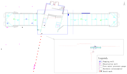
The station is a transfer station for two metros in Shanghai. It transfers to the existing metro in a “T” shape. The station is divided into two foundation pits, east and west, with the existing transfer section completed in the middle. The elevation of the bottom of the west foundation pit is −15.698 m, and the other is −16.015 m (Fig. 1).
2.2 Engineering geological and hydrogeological conditions
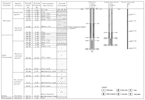
The station is located in the normal stratigraphic sedimentary area of Shanghai. The lithologies of the first aquifer and the second aquifer are mainly composed of silty sand or medium coarse sand. The lithology of the first aquitard is composed of dark green hard soil and thick silty soft soil. The thickness of two confined aquifers, which are interconnected with each other, is about 60 m (Fig. 2). The top elevation of the aquifer is −23.54 to −25.77 m, the bottom elevation is −83.00 to −87.00 m, and the groundwater level is −1.24 to −1.84 m. There is a dark green hard soil layer and a thick silty soft soil layer in the upper part of aquifer.
3.1 Integrated design
At present, most of the design of the foundation pit enclosure is based on structural stability, economy and technology, but the land subsidence caused by deep foundation pit dewatering does not play much of a role. Integrative design considers the engineering of the geological and hydrogeological conditions, the characteristics of the foundation pit enclosure, the drawdown of groundwater level outside the pit, and the requirements of land subsidence control, etc, and analyzes the characteristics of the groundwater seepage field caused by foundation pit dewatering and its influence on land subsidence by numerical simulation, field testing and engineering.
Because the bottom of the confined aquifer in the foundation pit project is deeply buried, it is difficult to cut off the hydraulic connection between the confined aquifer inside and outside the foundation pit by using the waterproof curtain that is made of reinforced concrete. Therefore, it is necessary to choose the most efficient balance point between the depth and economy of waterproof curtain. Based on the pumping test data, a numerical model is established to analyze the dropdown of groundwater level and the land subsidence outside the foundation pit with different depths of the waterproof curtain (Fig. 3; Luo, 2008).
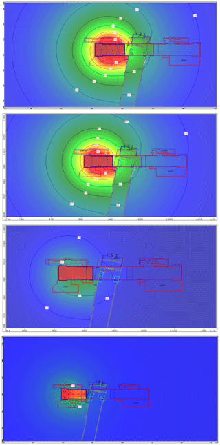
Figure 3Contour map of groundwater level drawdown after foundation pit dewatering 90 d later under different depths (34, 37, 43, 48 m) of the waterproof curtain conditions (unit: m).
According to the comparison of drawdown under different depths of the waterproof curtain, the drawdown outside the pit decreases when the depth of the waterproof curtain is increased, but the trend of water level drawdown outside the pit is not obvious when the depth of the waterproof curtain is greater than a certain value, and the efficiency of the waterproof curtain is reduced. The waterproof curtain depth in the foundation pit is finally determined to be 43 m through the optimization solution.
As the station was built and opened to traffic, the waterproof curtain was constructed in the early stages.
Restricted by construction conditions and economic conditions, the metro jet system construction method is used only in the north and east side to increase the depth of the waterproof curtain to 43 m (Wang et al., 2009, 2013).
3.2 Information control
In the process of a dewatering operation, the automatic monitoring device of groundwater level and wireless transmission technology are used to start the dewatering well and control the pumpage to meet the necessary dewatering requirements. Through the software of an automatic control system, users can monitor multiple terminal device remotely in the central control room. In this way the automation and convenient management of water level data information is realized.
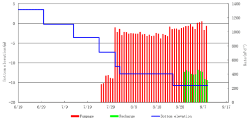
By connecting multiple automatic monitoring devices of groundwater level to data logger equipment, the real-time or historical monitoring data of one or more devices by monitoring well name (or area) can be displayed in tables or on graphs. At the same time, it supports SMS and ring wake-up. Compared with the design depth, when the water level of the monitoring well reaches the design drawdown, it can change the pumpage of the foundation pit freely by adjusting the valve. Compared with the design depth, the pumpage of the foundation pit presents a step-by-step growth (Fig. 4).
3.3 Artificial recharge
In the process of foundation pit construction, effective control of groundwater level around the pit should be the key to control land subsidence caused by dewatering. Recharge is the most direct way to control the drawdown of groundwater level caused by foundation pit dewatering, and this method should have the advantages of low cost, a short construction period, simple equipment and easy control of environmental pollution (Mohammad, 2007).
The depth of the waterproof curtain has increased to 43 m only on the north and east side, but the original depth is maintained on the south side. Therefore, in order to control the land subsidence, it is proposed to arrange six recharge wells outside of the waterproof curtain. However, restricted by the actual construction conditions of the site around the project, only two recharge wells are allowed to be arranged on the north side of the construction site; therefore, a total of five recharge wells are arranged. The filter pipe of recharge well is located at 30 to 40 m, which is slightly lower than the depth of pumping well and the waterproof curtain. In this groundwater artificial recharge, the groundwater extracted from pumping wells is treated by a groundwater purification processor and sent to recharge wells. There is no blockage of the filter pipe.
In order to guide the implementation of land subsidence prevention measures, groundwater level observation wells, land subsidence monitoring points, borehole extensometers and pore water pressure gauges are set up around the foundation pit to comprehensively monitor the changes of groundwater level and land subsidence during the process of foundation pit dewatering.
4.1 Groundwater level
The groundwater level in observation wells decreases during the period of foundation pit dewatering. Figure 5 shows that the drawdown more than 60 m away from the foundation pit is about 5.0 m, and the drawdown more than 200 m away from the foundation pit is about 2.5 m. Because the depth of the waterproof curtain is not increased on this side, the hydraulic gradient is gentle and the influence range is also wide by numerical calculation. It is theoretically inferred that the groundwater level falls about 1 m beyond 500 m.
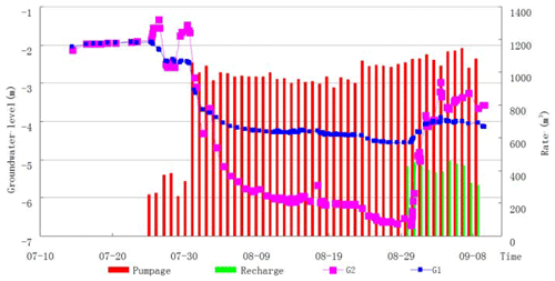
Figure 5The observation data of groundwater level (G1 is an observation well 60 m away from the foundation pit and G2 is an observation well 200 m away from the foundation pit).
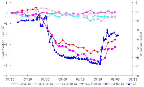
After a month and a half of dewatering, artificial recharge has been started, and then the groundwater level outside 60 m of foundation pit rises rapidly over 3 m, and the groundwater level outside 200 m of foundation pit rises about 0.5 m. It can be seen that the groundwater level rises obviously after artificial recharge, and the influence range is very far (Fig. 6).
4.2 Pore water pressure
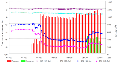
The variation of pore water pressure is similar to that of groundwater level. The pore water pressure of the confined aquifer outside the pit decreases significantly during dewatering and rises significantly after recharge. Because of the different permeability between the first aquifer and the second aquifer, the change of pore water pressure is different, but it decreases gradually with the prolongation of dewatering time and tends to be stable after 10 d of dewatering. After artificial recharge, the pore water pressure of the confined aquifer outside the pit also rises rapidly, and the pore water pressure of the first aquifer (KY4) rises more obviously than that of the second aquifer (KY5). The pore water pressure of overlying clayey soil decreases only a little. The pore water pressure of muddy clay is basically unchanged (KY3), and the clay under this layer changes slightly (KY4). It can be seen that the influence of dewatering in the vertical direction has become weak when it reaches the top of dark green hard soil layer, which is about 8 m away from the top of aquifer (Fig. 6).
4.3 Land subsidence
The monitoring time curve of land subsidence at typical monitoring points shows that the amount of land subsidence around the foundation pit increases gradually during excavation and dewatering. The accumulated land subsidence about 60 m away from the foundation pit is close to 5 mm and the accumulated land subsidence of the farthest monitoring points (about 600 m away from the foundation pit) is close to 2 mm after a month and a half of dewatering (Fig. 7). After opening the recharge, obvious rebound is observed from the monitoring points close to the recharge well. The maximum ground rebound is more than 2 mm. The land subsidence monitoring data of the farthest monitoring point show that the land does not rebound, but the subsidence trend is obviously slowed down and tends to converge.
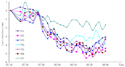
Figure 7The observation data of land subsidence for typical monitoring points south of foundation pit (the distances between the monitoring points and the foundation pit are 40.5, 84.3, 100.9, 153.8, 207.8, 281.7 and 387.9 m respectively).
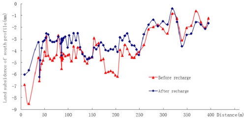
From the spatial distribution of land subsidence, the land subsidence in the area about 250 m away from the foundation pit is high, possibly reaching 4 mm. With the increase of the distance from the foundation pit, the land subsidence slows down obviously. The land subsidence in the area about 600 m away from the foundation pit is more than 1 mm. It can be seen that the influence range of the land subsidence caused by this project can reach 600 m. The monitoring points on the whole profile rebound obviously after the start of recharge. It can be seen that group well recharge can effectively reduce land subsidence (Fig. 8).
Figure 9 shows the graph of deformation for individual layers and groundwater level (about 60 m away from foundation pit). The graph shows that the dewatering aquifer is the main deformation soil layer in the process of foundation pit dewatering. The maximum accumulated deformation is about 4 mm. Because the lithology of the overlying clay layer is dark green hard soil which has the characteristics of low permeability and low compressibility, the deformation of this layer is not obvious.
Conclusions can be drawn by the above analyses. (1) The integrated design of foundation pit dewatering and a waterproof curtain, information control, groundwater artificial recharge, and other land subsidence control technologies covering the whole life cycle of foundation pit engineering were applied to the foundation pit of a typical subway station in Shanghai. (2) The drawdown of groundwater outside the foundation pit is controlled within 5 m and the land subsidence is controlled within 6 mm. The measured data of groundwater level, pore water pressure and land subsidence show a good effect on land subsidence control. (3) It would be necessary to carry out further theoretical research on land subsidence control of deep foundation pit dewatering, such as the deformation mechanism of aquifers and aquitards during dewatering and recharge, the accurate prediction of land subsidence, and the control conditions of groundwater level outside the foundation pit.
Data are not publicly available.
The author declares that there is no conflict of interest.
This article is part of the special issue “TISOLS: the Tenth International Symposium On Land Subsidence – living with subsidence”. It is a result of the Tenth International Symposium on Land Subsidence, Delft, the Netherlands, 17–21 May 2021.
The author thanks the Science and Technology Commission of Shanghai Municipality (funding no. 12231200700) for the financial assistance given to this work.
This research has been supported by the Science and Technology Commission of Shanghai Municipality (grant no. 12231200700).
Liu, C. P. Y. L.: Characterization of land subsidence in the Choshui River alluvial fan, Taiwan, Environ. Geol., 45, 1154–1166, https://doi.org/10.1007/s00254-004-0983-6, 2004.
Luo, Z. Z. Y.: Finite element numerical simulation of three-dimensional seepage control for deep foundation pit dewatering, J. Hydrodyn., 20, 596–602, https://doi.org/10.1016/S1001-6058(08)60100-6, 2008.
Mohammad, A. M. M. H.: Declining groundwater level and aquifer dewatering in dhaka metropolitan area, bangladesh causes and quantification, Hydrogeol. J., 15, 1523–1534, 2007.
Wang, J. X., Hu, L. S., and Wu, L. G.: Hydraulic barrier function of the underground continuous concrete wall in the pit of subway station and its optimization, Environ. Geol., 57, 447–453, https://doi.org/10.1007/s00254-008-1315-z, 2009.
Wang, J. X., Feng, B., and Yu, H.: Numerical study of dewatering in a large deep foundation pit, Environ. Earth Sci., 69, 863–872, https://doi.org/10.1007/s12665-012-1972-9, 2013.
Wu, Y. Q., Zhang, J. S., and Li, Z.: Mechanism analysis of land subsidence due to groundwater withdrawal and control measures, J. Rock Soil Mech., 26, 1582–1586, https://doi.org/10.16285/j.rsm.2005.10.011, 2005.


