the Creative Commons Attribution 4.0 License.
the Creative Commons Attribution 4.0 License.
An engineering approach to quantify geomechanical safety factors in UGS programs
Giovanni Isotton
Pietro Teatini
Raffaele Stefanelli
Massimiliano Ferronato
Carlo Janna
Matteo Cerri
Timur Gukov
Underground Gas Storage (UGS) has become one of the most widely used practices to cope with seasonal peaks in energy consumption. The planning of any new UGS facility, or its upgrading to increase the working gas volume and reservoir performance, must be supported by an evaluation of possible induced effects on the environment. From a geomechanical point of view, storage activity results in a cyclic change in stress and deformation in the reservoir rock and the surrounding formations. The main environmental issues to be accounted for when natural fluid pore pressure is planned to be exceeded are the following: (a) the differential displacements at the land surface possibly mining the integrity of ground structure; (b) the integrity of the reservoir and caprock; (c) the possible reactivation of faults, if the target reservoir is located in a faulted basin; and (d) the vertical upheaval and land subsidence that can impact on the surface drainage network in low lying coastal areas. We present an original methodology for evaluating the geomechanical safety of UGS activities using an approach derived from what is traditionally applied in the structural design of buildings. A safety factor, a margin of security against risks, is defined for each of the geomechanical issues listed above. First, a 3D FE-IE numerical model is developed to reproduce the stress and displacement due to the UGS program under evaluation. Then the reservoir pressure is increased until the “failure” condition is reached allowing to evaluate how far the project designed condition is from the above limit. The proposed approach is applied to Romagna, a depleted gas reservoir in Northern Italy converted to UGS, with the aim of investigating the safety of the project to increase the reservoir pressure up to 120 % pi, where pi is the original reservoir pressure before the start of primary production. The 3D geomechanical model has been developed using recent 3D seismic data, land displacements by InSAR, lab tests on reservoir and caprock samples, in-situ Modular Formation Dynamic Tester (MDT) stress tests, and large background information acquired from other UGS reservoirs located in the same sedimentary basin. The analysis outcome has revealed that the investigated scenario is safe, with safety factor larger than 1, in the range from 1.2 to 4. The most critical condition (the smallest safety factor) has been obtained in relation to the mechanical integrity of the reservoir formation, under very conservative conditions (cohesion = 0, friction angle = 30∘).
- Article
(380 KB) - Full-text XML
- BibTeX
- EndNote
Because of the need to cope with seasonal peaks in energy consumption, the interest to develop new underground gas storage (UGS) facilities is continuously growing. The widespread use of UGS is followed by a growing concern of Government authorities and Public opinion about its geomechanical issues, especially subsidence and induced (micro-) seismicity. Thus, there is a growing need to combine advanced geomechanical analyses with more understandable evaluations.
Over the last decades a number of modelling applications were developed to characterize the safety or the possible impact of UGS. A deterministic approach based on the evaluation of a few scenarios was followed by Teatini et al. (2011, 2019). Stochastic investigation by means of data assimilation procedure were implemented by Fokker et al. (2013), Jha et al. (2015) and Zoccarato et al. (2016).
In this work, a first attempt is made to develop an easily understandable approach to evaluate the safety of a UGS plant derived from what is traditionally applied in the structural design of buildings. For a number of safety issues detected in advance, the designed configuration Cd (in term of stress or deformation) is compared with the failure configuration Cf, and the safety factor is defined as the ratio Cf∕Cd.
Taking inspiration from this approach, the design and failure configurations as well as the safety factor related to the update of a UGS reservoir are evaluated with the aid of state-of-the-art numerical models.
2.1 Geomechanical issues definition
The UGS activities induce changes of the stress and strain fields, with the earlier that remains substantially confined within the reservoir formation and the nearest portion of the surrounding rocks and the latter that spreads to the land surface (Teatini et al., 2011; Castelletto et al., 2013). An exhaustive evaluation of the possible impacts of a UGS field located in a flat coastland must consider the following safety issues (I):
-
the gradient of the displacement field at the land surface (I1): the subsidence and/or differential displacements can weaken the load-bearing capacity of buildings and/or structures above the reservoir and surrounding areas, triggering of cracks or deformations that are unacceptable in relation to the integrity of the structure. The multi-level masonry buildings are the structures most sensitive to differential displacements, with the most cautious limit for the vertical deformation gradient fixed at i.e. 5 cm per 100 m (Viggiani, 2003). The limits for all other types of structure are higher than the latter (Simeoni et al., 2017), even 100 times for flexible buildings such as those made of steel;
-
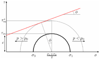
the mechanical integrity of the reservoir rock and the neighbouring formations (I2): the generation of fractures/cracks due to shear failure can cause micro-seismicity or compromise the hydraulic seal of the caprock. Using a Mohr representation of the stress state, two coefficients ψ and χ can be implemented to quantify the gap between the actual stress state induced in the reservoir and caprock, and the tensile and shear limit conditions (Castelletto et al., 2013; Teatini et al., 2014). The coefficient ψ, which is related to tensile failure, is defined as follows:
where σ3 is the minimum principal effective stresses and σ3,0 is the minimum compression stress in undisturbed conditions. The χ coefficient, which is related to shear failure, is defined as:
where τm is the current shear stress that develops at a given tensional regime and is the maximum shear stress at failure, i.e. the minimum distance between the Mohr circle and the failure envelope. A graphical interpretation of the two coefficients is shown in Fig. 1. The failure condition is reached whenever ψ=0 and/or χ=0;
-
reactivation of faults near the field (I3): pre-exisiting faults crossing the field or located in its surroundings may be reactivated due to the stress change variation and induced (micro-) seismicity. The fault reactivation may also be investigated through the Mohr-Coulomb failure criterion (Labuz and Zang, 2012):
with σn and τ the normal and shear stresses, respectively, acting on the fault surfaces, ϕ and c the fissure friction angle and cohesion, respectively, and τL the shear stress limit. When τ equates or exceeds the previous limit, the fault can slip. Moreover, in case of a tensile normal stress, the fault can open;
-
the hydraulic efficiency of the drainage network (I4): surface movements due to pore pressure change in the UGS reservoir modify the elevation of the land surface above the UGS reservoir, possibly reducing the hydraulic efficiency of the natural and artificial drainage network in the area. This could cause a higher risk of flooding (less hydraulic safety) or the need for larger system of pumping stations or water containment basins, or embankment raise.
2.2 Safety factor definition
Because of the great economical interest to increase the working gas volume as much as possible, UGS plans in Italy generally consider the possibility of increasing the maximum gas pore pressure at the end of the injection phase. For example, in the Lombardia reservoir, which is a UGS field in operation since 1987 in the sedimentary Po river basin, the maximum pore-overpressure was planned to be pushed from the current 103 % pi, where pi is the gas pore pressure prior to the field development, to 107 % pi and, later on, possibly till to 120 % pi. This would allow an increase in the stored gas volume by approximately 65 % and 180 % relative to the 103 % pi storage value (Teatini et al., 2011).
In relation to the possibility of increasing the working gas volume the geomechanical safety is evaluated by means of a Safety Factor (SF) for each of the safety issue listed above. SF is defined as follows as:
where Δp is the planned reservoir pressure variation during the UGS activities and Δpf is the reservoir pressure variation that reaches the failure condition, i.e. causes damages to surface structures/infrastructures, fractures in the reservoir formation and/or the caprock, fault reactivation, and unacceptable loss of hydraulic efficiency of the drainage network. The larger than 1 SF is, the safer the planned UGS activities are in relation to that specific issue.
The pressure distribution Δp, as provided by a 3D dynamic reservoir simulator (e.g., Eclipse) for the planned UGS scenario, is increased through a multiplicative factor until the “failure” condition (Δpf) is reached, allowing to evaluate how far the project designed condition is from the above limit. The geomechanical issues defined above are computed with the aid of a 3D geomechanical model of subsurface where the reservoir is located and a 1D hydrological-hydraulic model of the drainage network in the area above the UGS field.
The proposed approach is applied to Romagna, a depleted gas reservoir in Northern Italy converted to UGS. The UGS project plans to increase the reservoir pressure up to 120 % pi.
3.1 Mathematical model
The stress and strain variations associated to the UGS activities in Romagna were simulated using the M3E_GEPS3D (Geomechanical visco-Elasto-Plastic Simulator – 3D) simulator, an in-house developed code (Gambolati et al., 2001; Janna et al., 2012; Spiezia et al., 2017), presently maintained by M3E S.r.l. (https://www.m3eweb.it/geomechanical-engineering/, last access: 17 April 2020). The code is based on finite elements (FEs) and interface elements (IEs). FEs solves the equilibrium equations governing the deformation of the continuous medium (Biot, 1941) and allows to compute the stress field through appropriate constitutive relations. IEs are implemented for fault discretization making use of Lagrange multipliers (Franceschini et al., 2016, 2019). The main parameters of the geomechanical model are the reservoir stiffness of the porous medium E, the Poisson ratio v, the fault cohesion c and friction angle ϕ.
From the hydrological-hydraulic point of view, the prediction of the efficiency variation of the surface drainage network possibly caused by the movements of the ground surface due to UGS was simulated by means of the codes HEC-HMS (USACE-HEC, 2010) and HEC-RAS (USACE-HEC, 2016) developed by the U.S. Army Corps of Engineers – Hydrologic Engineering Center.
3.2 Model set-up
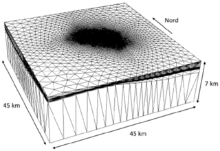
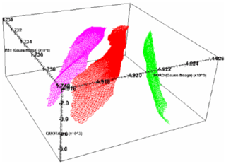
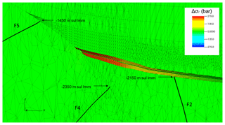
The geometry of the geomechanical model is shown in Fig. 1. The domain has an areal extension of 45×45 km with the Romagna reservoir located in a central position. The 3D grid, which is formed by nodes, tetrahedral, and IEs, was developed using the automatic grid generator TetGen (Si, 2008). The domain is confined by the ground surface above and a rigid basement 7 km deep below. It is discretized to accurately reproduce the geological setting, e.g., the pinch-out closures of the geological levels, the volumes of the mineralized pools, the GWC elevation and the geometries of the aquifers hydraulically connected to the reservoir. The three faults closest to the reservoir, and thus affected by a larger stress perturbation during UGS activities, are included into the geomechanical model (Fig. 2). Standard conditions with zero displacement on the outer and bottom boundaries are prescribed, while the land surface is a no-stress boundary. The large modeling domain relative to the reservoir dimensions assures that the disturbance does not reach the boundary.
The porous medium characterization is performed using a constitutive relationship developed for the Northern Adriatic sedimentary basin by a statistical analysis of radioactive marker measurements. The relation provides the oedometric soil compressibility cM as a function of the effective vertical stress σz (Baù et al., 2002, Ferronato et al., 2013). In particular, the “expected” cM relationship is used:
with cM in MPa−1 and σz in MPa. cM is related to soil stiffness E and Poisson's ratio through a well-known relation. Larger values of cM, e.g., the 95 % upper bound provided by the statistical data processing, were also used, but the computed surface displacements were not consistent with the available InSAR measurements on the reservoir area. For the Poisson ratio, a value of 0.3 was used according to bibliography data.
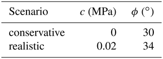
The fault mechanical characterization was performed according to the results of lab tests carried out on reservoir and caprock samples and in-situ MDT stress tests. In particular, the two sets of values provided in Table 1 were used in the geomechanical simulations.
Table 1Mechanical properties of the faults derived from lab and in-situ tests on the rock of the Romagna reservoir.
A plane view of the hydrological-hydraulic model is shown in Fig. 3. The hydrologic setting and the geometry of the channels were defined according the data provided by the “Consorzio di Bonifica della Romagna Occidentale” (2001).
3.3 Numerical results
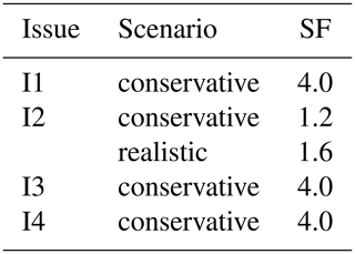
The results of the numerical analyses are summarised in terms of safety factors in Table 2. The model outcomes reveal that the planned UGS program with a maximum overpressure at 120 % pi is safe, i.e., characterized by a Safety Factor larger than 1 for all the geomechanical issue addressed in the analysis. Issues I1, I3 and I4 are characterized by the maximum possible value of SF, SF = 4. In fact, the reservoir pressure cannot be increased to values larger than 180 % pi since this would result in a non-physical situation where the rock in the reservoir is subject to tensile stress (Fig. 5).
The most critical condition (the smallest SF) is obtained in relation to the mechanical integrity of the reservoir formation (issue I2). However, even in the conservative scenario, the pressure variation planned by the UGS activities is 20 % lower than the critical condition (SF = 1.2).
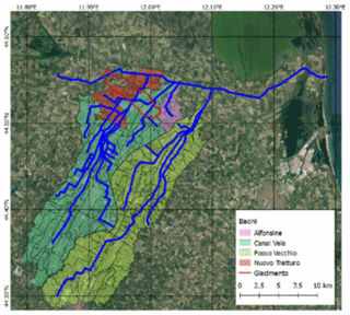
Figure 4Map showing the main hydraulic network (in blue) above the Romagna reservoir (in red). The coloured areas highlight the various hydrologic catchments.
A methodology for assessing the safety of UGS programs has been developed using an approach derived from structural design of buildings.
First, the main geomechanical issues have been delineated and a definition of the safety factor for UGS activities has been proposed.
Starting from the outcome of a dynamic reservoir simulator for the planned UGS program in terms of pressure distribution, for each issue, the safety factor has been calculated with the aid of a 3D geomechanical model and a 1D hydrological-hydraulic model.
The procedure has been then applied to the Romagna UGS reservoir in the Northern Italy with a positive outcome in relation to a possible UGS program at 120 % pi. The study has shown how this procedure can be easily combined with the classic geomechanical analysis to summarize and translate advanced notions in terms commonly used in engineering.
This is a first attempt to facilitate understanding by Government control authorities and the Public opinion. Future applications to other cases could provide the starting point for safety guidelines development or updating.
The public data can be downloaded from the website of the Ministry of the Environment of the Italian Republic: https://va.minambiente.it/ (last access: 17 April 2020).
All the authors have contributed in equal measure.
The authors declare that they have no conflict of interest.
This article is part of the special issue “TISOLS: the Tenth International Symposium On Land Subsidence – living with subsidence”. It is a result of the Tenth International Symposium on Land Subsidence, Delft, the Netherlands, 17–21 May 2021.
Baù, D., Ferronato, M., Gambolati, G., and Teatini, P.: Basin-scale compressibility of the Northern Adriatic by the radioactive marker technique, Geotechnique, 52, 605–616, 2002.
Biot, M. A.: General theory of three-dimensional consolidation, J. Appl. Phys., 12, 155–164, 1941.
Castelletto, N., Gambolati, G., and Teatini, P.: Geological CO2 sequestration in multi-compartment reservoirs: Geomechanical challenges, J. Geophys. Res.-Sol. Ea., 118, 2417–2428, https://doi.org/10.1002/jgrb.50180, 2013.
Consorzio di Bonifica della Romagna Occidentale: Studio idrologico ed idraulico del Canale di Bonifica in Destra di Reno (collettore generale di tutti i Comparti di scolo del Consorzio) in condizioni di piena eccezionale: verifica del sistema nello stato di fatto attuale e delle configurazioni progettuali prospettate per il miglioramento della capacità di trasferimento idrico nel cavo, 2001 (in Italian).
Ferronato, M., Castelletto, N., Gambolati, G., Janna, C., and Teatini, P.: II cycle compressibility estimate from satellite measurements, Geotechnique, 63, 479–486, https://doi.org/10.1680/geot.11.P.149, 2013.
Fokker, P. A., Wassing, B. B. T., van Leijen, F. J., Hanssen, R. F., and Nieuwland, D. A.: Data assimilation of PS-InSAR movement measurements applied to the Bergermeer gas field, Conference Proceedings, International EAGE Workshop on Geomechanics and Energy, https://doi.org/10.3997/2214-4609.20131971, 2013.
Franceschini, A., Ferronato, M., Janna, C., and Teatini, P.: A novel Lagrangian approach for a stable numerical simulation of the mechanics of faults, J. Comp. Phys., 314, 503–521, 2016.
Franceschini, A., Castelletto, N., and Ferronato, M.: Block preconditioning of fault/fracture mechanics saddle-point problems, Comput. Methods Appl. Mech. Eng., 344, 376–401, 2019.
Gambolati, G., Ferronato, M., Teatini, P., Deidda, R., and Lecca, G:. Finite element analysis of land subsidence above depleted reservoirs with the pore pressure gradient and total stress formulations, Int. J. Numer. Anal. Mod., 25, 307–327, 2001.
Janna, C., Castelletto, N., Ferronato, M., Gambolati, G., and Teatini, P.: A geomechanical transversely isotropic model of the Po River basin using PSInSAR derived horizontal displacement, Int. J. Rock Mech. Mining Sci., 51, 105–118, 2012.
Jha, B., Bottazzi, F., Wojcik, R., Coccia, M., Bechor, N., McLaughlin, D., Herring, T., Hager, B. H., Mantica, S., and Juanes, R.: Reservoir characterization in an underground gas storage field using joint inversion of flow and geodetic data, Int. J. Num. Anal. Methods Geomech., 39, 1619–1638, 2015.
Labuz, J. F. and Zang, A.: Mohr–Coulomb failure criterion, Rock Mech. Rock Eng., 45, 975–979, 2012.
Si, H.: Adaptive tetrahedral mesh generation by constrained Delaunay refinement, Int. J. Numer. Methods Eng., 75, 856–880, 2008.
Simeoni, U., Tessari, U., Corbau, C., Tosatto, O., Polo, P., and Teatini, P.: Impact of land subsidence due to residual gas production on surficial infrastructures: the Dosso degli Angeli field study (Ravenna, Northern Italy), Eng. Geol., 229, 1–12, https://doi.org/10.1016/j.enggeo.2017.09.008, 2017.
Spiezia, N., Ferronato, M., Janna, C., and Teatini, P.: A two-invariant pseudoelastic model for reservoir compaction, Int. J. Num. Anal. Meth. Geomech., 41, 1870–1893, 2017.
Teatini, P., Castelletto, N., Ferronato, M., Gambolati, G., Janna, C., Cairo, E., Marzorati, D., Colombo, D., Ferretti, A., Bagliani, A., and Bottazzi, F.: Geomechanical response to seasonal gas storage in depleted reservoirs: A case study in the Po River basin, Italy, J. Geophys. Res., 116, F02002, https://doi.org/10.1029/2010JF001793, 2011.
Teatini, P., Castelletto, N., and Gambolati, G.: 3D geomechanical modeling for CO2 geological storage in faulted formations. A case study in an offshore northern Adriatic reservoir, Italy, Int. J. Greenh. Gas Con., 22, 63–76, 2014.
Teatini, P., Ferronato, M., Franceschini, A., Frigo, M., Janna, C., Zoccarato, C., and Isotton, G.: Gas storage in compartmentalized reservoirs: a numerical investigation on possible “unexpected” fault activation, in: 53rd US Rock Mechanics/Geomechanics Symposium, American Rock Mechanics Association, paper# ARMA 19-1991, 2019.
USACE-HEC: Hydrologic Modeling System, HEC-HMS v3.5 – User's Manual, US Army Corps of Engineers, Hydrologic Engineering Center, Tech. Report CPD-74A, 2010.
USACE-HEC: River Analysis System, HEC-RAS v5.0 – User's Manual, US Army Corps of Engineers, Hydrologic Engineering Center, Tech. Report CPD-68, 2016.
Viggiani, C.: Fondazioni, Helvelius Edizioni, Benevento, Italy, 2003 (in Italian).
Zoccarato, C., Baù, D., Ferronato, M., Gambolati, G., Alzraiee, A., and Teatini, P.: Data assimilation of surface displacements to improve geomechanical parameters of gas storage reservoirs, J. Geophys. Res.-Solid Earth, 121, 1441–1461, doi:10.1002/2015JB012090, 2016.


