the Creative Commons Attribution 4.0 License.
the Creative Commons Attribution 4.0 License.
Ground subsidence due to the backfill pressure in tunnel boring machine
Chang-Kyun Ahn
Seok-Won Lee
In shield tunnel boring machine constructions, backfill pressure affects surface settlement and the stability of other underground structures nearby. Therefore, it is essential to pre-calculate backfill pressure in the design stage. This study examines and compares the seven internationally known backfill pressure calculation theories and calculates and analyzes the backfill pressures in six virtual ground conditions. The calculated backfill pressure increased as the ground cover increased, but the increase rate decreased. Also, this study performs a numerical analysis to identify the impact on ground settlement and tunnel crown settlement. In the end, settlement was more impacted by face pressure than backfill pressure in the unsaturated and saturated ground conditions. Also, as the ground cover increased, the impact of backfill pressure decreased, and as the applied face pressure decreased, the impact of backfill pressure increased.
- Article
(267 KB) - Full-text XML
- BibTeX
- EndNote
Recently, tunnel excavations through the blasting method cause many complaints in cities due to noise and vibrations, leading to the rise of shield TBM (tunnel boring machine) that assembles segment lining while preventing the collapse of top ground with a shield at the same time as tunnel excavation. The shield TBM method is advantageous for urban excavations because of its less noise and vibration, and guarantees the stability of the structures at the top of the tunnel impacted by ground movement at the time of tunneling. Moreover, the method has less risk of underground water inflow into the tunnel during tunnel excavation even under a high ground water pressure(level) in an unconfined aquifer.
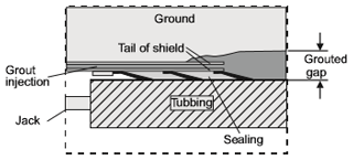
With this shield TBM method, an annular empty space is created inevitably(hereafter referred to as tail void) caused by the difference between the outer diameter of the shield and the outer diameter of the primary segment lining at the time of tunnelling, due to the mechanical characteristics of shield machine as shown in Fig. 1. Therefore, backfilling the tail void is an essential step for the shield TBM method. Backfill pressure refers to the pressure injecting the backfilling material into the tail void to prevent surface settlement during the shield TBM excavation. Too much or too small backfill pressure may cause uplift or settlement of the ground, affecting the stability of the top structure. Also, such pressure may transform the ground condition, or affect other underground structures in the adjoining underground space, such as the foundation, tunnel, or pipes. Therefore, appropriate backfill pressure according to the ground conditions is important to apply the shield TBM method safely.
This study examines and analyzes the backfill pressure calculation theories (models) that have been studied and suggested so far. By applying these models, this study calculates the backfill pressure for each model to prevent surface settlement of the top ground excavated through a shield TBM at the design stage in various virtual ground conditions. Afterwards, the calculated backfill pressure was applied to a numerical analysis to comparatively analyze the impact of the differences in backfill pressures in different models on the settlement of the ground and tunnel crown according to the ground conditions and ground cover.
Backfill pressure is estimated based on the shield TBM face pressure (lateral earth pressure), or corresponding to the vertical (normal) stress and water pressure applied to the TBM crown. Therefore, this study presents and analyzes the theories calculating backfill pressure in two types: theories based on the bearing pressure (face pressure, lateral earth pressure) applied to the tunnel face, and other theories based on the normal stress on the tunnel crown.
2.1 Backfill pressure calculation theories based on face pressure (lateral earth pressure)
Gatti and Cassani (2007) proposed the following methods to minimize surface settlement at the time of urban tunneling using the shield TBM: pressure control in the chamber, ground improvement, quantity control in the backfill injection and injection pressure management. They suggested that backfill injection pressure (σinj) should be calculated larger than the sum of the lateral earth pressure and water pressure applied to the center of the tunnel face in order for it to avoid convergence of the cavity and uniformly inject backfill materials. Their proposed calculation is shown in Eq. (1). Here, u, γ′, H, D means hydrostatic pressure, effective unit weight, ground cover of tunnel, tunnel diameter, respectively. K, the coefficient of earth pressure, is proposed to be larger than the static coefficient of earth pressure obtained through the Jaky's law.
Daniele Peila (personal communication, 2010) experientially proposed backfill pressure (σinj) as 0.5 bar plus the applied face pressure (σface, bar), as shown in Eq. (2).
Oyanguren Ramirez (personal communication, 2010) proposed backfill pressure (σinj) to be the applied face pressure (σface) multiplied by 1.5–1.8, as shown in Eq. (3).
Based on field data in Korea, generally the minimum backfill injection pressure (σinj) should be estimated 1–2 bar larger than the applied face pressure (σface, bar), as shown in Eq. (4). Such empirical method will be referred to as Empirical equation, hereafter.
2.2 Backfill pressure calculation theories based on normal stress
Wittke (2007) proposed backfill pressure (σinj) to be the value corresponding to the normal stress (σv) applied to the tunnel crown, as shown in Eq. (5).
Biosca and Bono (2008) proposed backfill pressure (σinj) as the value of the normal stress (σv, bar) applied to the tunnel crown added by 0.5–1.0 bar, as shown in Eq. (6).
Mollon et al. (2013) suggested backfill pressure (σinj) as the value of the normal stress (σv) applied to the tunnel crown multiplied by 1.2, as shown in Eq. (7).
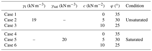
This study set six virtual ground conditions as shown in Table 1. There are three unsaturated ground conditions (Cases 1–3) where the tunnel is excavated above the ground water level, and three saturated ground conditions (Cases 4–6) where the tunnel is excavated below the ground water level. According to each case, soil (ground) properties such as unit weight (γ), cohesion (c), and internal friction angle (φ) were varied as shown in Table 1.
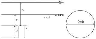
The tunnel excavation conditions were set as shown in Fig. 2. Ground cover (C in Fig. 2) was 30 m, tunnel excavation diameter (D=b in Fig. 2) was 8.3 m, and ground water level from tunnel crown (hw in Fig. 2, limited only to Cases 4–6) was 50 m.
This study applies the different backfill pressures calculated by a model to a numerical analysis to investigate the effect of the backfill pressure values on the ground and crown settlement (ground movement) caused by shield TBM tunnel excavation. For this, MIDAS GTS NX was selected as the ground numerical analytical program that similarly models the entire analysis process of shield TBM tunnel excavation in three dimensions. In addition, segment lining assembly and grout hardening processes were applied for each analysis step.
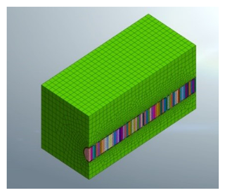
The ground conditions were applied for the numerical analysis: on even ground, 40 m width, 90 m length along the tunnel excavation direction, 8.3 m excavation diameter, 1.5 m excavated tunnel length, and three different ground covers (10, 20, 30 m representing C in Fig. 2) from the tunnel crown. The segment lining thickness and backfill grouting thickness were 30 and 20 cm, respectively. In the saturated conditions, the water level (hw in Fig. 2) was modelled at 50 m above from the tunnel crown. Figure 3 shows the numerical analysis model when the ground cover was 20 m.
4.1 Calculation of face pressure and backfill pressure applied to numerical analysis
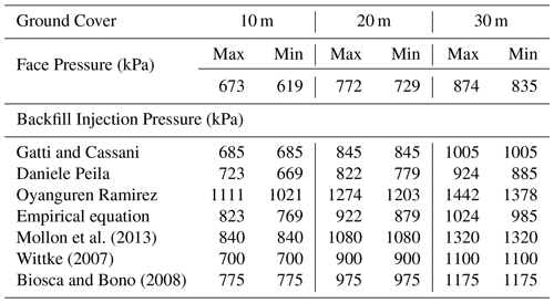
Face pressure and backfill pressure for numerical analysis were calculated in each of Case 1–6. The aforementioned seven theories (4 models based on face pressure + 3 models based on normal stress) were applied to calculate backfill injection pressure. Three models of Murayama (1966), Anagnostou and Kovari (1996), DIN 4085 (1987) and an empirical equation proposed by the Japanese Geotechnical Society were applied to calculate face pressure, after which the maximum and minimum face pressures were applied to each. This study investigated total six cases (Table 1), but the findings of Case 5 was only presented and discussed as the prime case. Other cases showed similar trends. Table 2 show the applied face pressure and backfill pressure for model according to the changes in ground cover in Case 5. In the numerical analysis, for example, the maximum and minimum face pressure were applied to each ground cover in Case 5. The seven backfill pressures were applied (total cases) to calculate ground settlement and crown settlement caused by shield TBM excavation.
4.2 Numerical analysis and results
4.2.1 Ground settlement
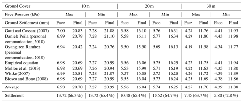
Table 3 shows the ground settlements for Case 5 under 10, 20 and 30 m ground covers, maximum and minimum face pressures, and seven backfill pressure models. “Face” in Table 3 indicates the settlement when the shield TBM face reaches the observation point and “Final” in Table 3 means the final settlement after tunnel excavation. When compared with Case 2 in unsaturated conditions (even though the results are not described in this paper due to the page restriction), the impact of applied face pressure and backfill pressure was smaller because water pressure mostly comprised the face pressure and backfill pressure calculations.
When compared in quantitative values, settlement by backfill grouting with 10 m ground cover, maximum face pressure, and Ramirez model (largest backfill pressure, 1111 kPa), was 13.48 mm (20.42–6.94 mm in Table 3), and with the Wittke model (smallest backfill pressure, 700 kPa), settlement was 13.82 mm (20.81–6.99 mm in Table 3). With minimum face pressure and Ramirez model (largest backfill pressure, 1021 kPa), settlement by backfill grouting was 13.52 mm, and with the Wittke model (smallest backfill pressure, 700 kPa), it was 13.79 mm. With maximum face pressure, settlement by changed backfill pressure was 0.00083 mm kPa−1 and with minimum face pressure, it was 0.00050 mm kPa−1. When obtained with the ground covers of 20 and 30 m and maximum face pressure applied, it was 0.00029 and 0.00013 mm kPa−1, respectively. With minimum face pressure, it was 0.00022 and 0.00024 mm kPa−1, respectively. As in the unsaturated conditions, the higher the ground cover increased, the lower the impact of backfill pressure decreased on ground settlement. Unlike in the unsaturated conditions, the impact was slightly larger with maximum face pressure.
4.2.2 Crown settlement
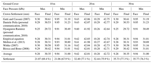
Table 4 shows the crown settlements for Case 5 under 10, 20 and 30 m ground covers, maximum and minimum face pressures, and seven backfill pressure models. The analysis shows similar results as in the case of ground settlement.
In the quantitative comparison, the settlement by the changed backfill pressure was 0.00197 mm kPa−1 with 10 m ground cover and maximum face pressure. It was 0.00118 mm kPa−1 with minimum face pressure. With the ground covers of 20 and 30 m, the settlement was 0.00027 and 0.00007 mm kPa−1 with maximum face pressure, respectively, and 0.00134 and 0.00117 mm kPa−1 with minimum face pressure, respectively. When compared with ground settlement in the unsaturated conditions, the impact of backfill pressure generally increased particularly within the maximum face pressure scenario, presumably because of the instant impact of backfill pressure on the crown, rather than ground, as the calculated backfill pressure increased according to face pressure.
4.2.3 Discussion on the numerical analysis
The impact of applied face pressure was bigger on final settlement on the ground and crown than that of backfill pressure both in the unsaturated and saturated conditions within the situation we applied. Ground movement by applied face pressure and applied backfill pressure was similar, but displacement immediately occurred as backfill pressure applies on the crown rather than ground. As ground cover increased on the ground and crown, the impact of backfill pressure decreased, and as the applied face pressure decreased, the impact of backfill pressure increased. However, in the unsaturated conditions, ground settlement increased as ground cover increased, but settlement decreased in the saturated conditions, presumably because relaxed load applied as ground cover increased. On the contrary, crown settlement increased both in the unsaturated and saturated conditions as the ground cover increased because crown settlement instantly reacted to the application of tunnel excavation and backfill pressure.
-
In the unsaturated conditions, the crown reacted more sensitively to backfill pressure than the ground. As the ground cover increased, the impact of backfill pressure on ground and crown settlement decreased. In the numerical analysis with varying face pressure, the impact of backfill pressure increased on ground settlement as face pressure decreased.
-
In the saturated conditions, the crown reacted more sensitively to backfill pressure than the ground, as in the unsaturated conditions. As the ground cover increased, the impact of backfill pressure decreased on ground and crown settlement.
-
In the unsaturated conditions, ground and crown settlement increased as the ground cover increased. But in the saturated conditions, ground settlement decreased as the ground cover increased. This is probably because it does not instantly react to tunnel excavation unlike crown settlement, and as the ground cover increased, a relaxed load applies to decrease settlement. On the contrary, crown displacement is instant according to the application of tunnel excavation and backfill pressure, leading to increasing settlement according to the ground cover.
The data are not publicly accessible. Every researcher can get the same results if they conduct the same numerical simulation following the same procedure as we do.
CKA conducted the numerical simulation and SWL provided the idea and basic theory.
The authors declare that they have no conflict of interest.
This article is part of the special issue “TISOLS: the Tenth International Symposium On Land Subsidence – living with subsidence”. It is a result of the Tenth International Symposium on Land Subsidence, Delft, the Netherlands, 17–21 May 2021.
This research has been unded by the Ministry of Land, Infrastructure, and Transport of the Korean government (Construction Technology Research Program, grant no. 19SCIP-B105148-05).
Anagnostou, G. and Kovari, K.: Face stability conditions with earth-pressure-balanced shields, Tunn. Undergr. Sp. Tech., 11, 165–173, 1996.
Biosca, F. and Bono, R.: Construccion de la linea 9 del metro de Barcelona, Obras Urbanas magazine, Wiley, 2008.
DIN 4085, Baugrund-Berechnung des Erddrucks, 1987.
Gatti, M. C. and Cassani, G.: Ground loss control in EPB TBM Tunnel excavations, Proceeding of the world tunnel congress, Prague, 1141–1146, 2007.
Moeller, S. C.: Tunnel induced settlements and structural forces in linings, PhD Thesis, Institute for Geotechnical Engineering of the University of Stuttgart, Berlin, 2006.
Mollon, G., Dias, D., and Soubra, A.-H.: Probabilistic analyses of tunneling-induced ground movements, Acta Geotechica, 8, 181–199, 2013.
Murayama, S.: Review of excavation performance of mechanized shield from viewpoint of soil mechanics, Proceedings of the 1st Japan national conference on soil mechanics and foundation engineering, 1966.
Wittke, W.: Stability analysis and design for mechanized tunnelling, WBI-PRINT6, 2007.


